How I built my Dactyl Manuform Keyboard
I’ve been obsessed with split keyboards since I started developing wrist pain a few years ago and figured out that a better posture - keeping your wrists straight and your arms shoulder length apart - during long typing sessions can work wonders.
I used my Microsoft Sculpt keyboard for over 4 years, but it started showing its age with the fabric peeling off and some keys growing stiff. Plus, it wasn’t a fully split keyboard like the Keyboardio or the Moonlander - both boards that I’ve been hungrily eyeing since forever. Unfortunately, buying one of those wasn’t an option for me due to Customs fees. It’s an absolute nightmare to navigate Customs in India, with fees ranging from 0% to 77% (!!) of the total price, completely depending on the mood of the individual officer inspecting the package at arrival. Since there’s no way to tell how much I’d have to pay before hand, I had to plan for the worst - and there’s no way in hell I’m paying 177% + shipping on a keyboard that’s already crazy expensive. I had no choice but to try and build my own split keyboard.
Enter the Dactyl Manuform ❤️
Planning and Sourcing parts
Huge thanks to Kevin Eckert for his build vlog, it was the only reason I could get up the confidence to try something this big by myself.
These were the pieces I needed to figure out how to source:
- The outer plastic body
- Switches
- Keycaps
- Microcontrollers for the two halves
- Firmware to flash on the keyboard
- Misc. electrical supplies:
- Connecting wires
- Legs for the microcontroller (makes it possible to solder wires onto it)
- Batteries and battery holders (since I wanted to go wireless)
- Screws and standoffs for sealing the whole thing up once done
Outer body
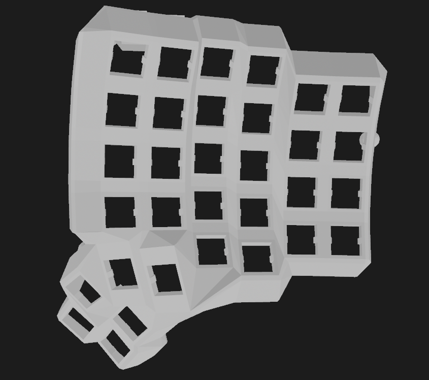
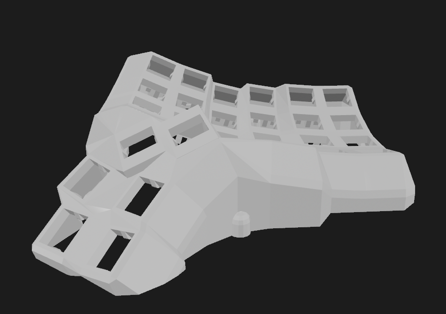
Thanks the beautiful README on the Dactyl Manuform repo, I was able to view a to-scale render of the case on my computer before printing. The exact specs need to be configured manually, while the repo provides a default config I felt by looking at the render that I would need to tune it differently for my larger hands. The only foolproof way to do this is to try out some config, 3D print it and try it out, and make changes as required. Unfortunately 3D printing is prohibitively expensive in India, so I had to eyeball it looking at the renders in OpenSCAD.
These are the parameters I adjusted in the config:
- No. of keys - The default is a 4x5 board (40% board, pics are in the repo). I prefer to have more keys so I can configure shortcuts, macros etc. so I went with a 6x7 board.
- Shell height - Since its a tilted board, we need to specify an initial height (at the lowest point) and a tilting angle that would determine the height at the other end.
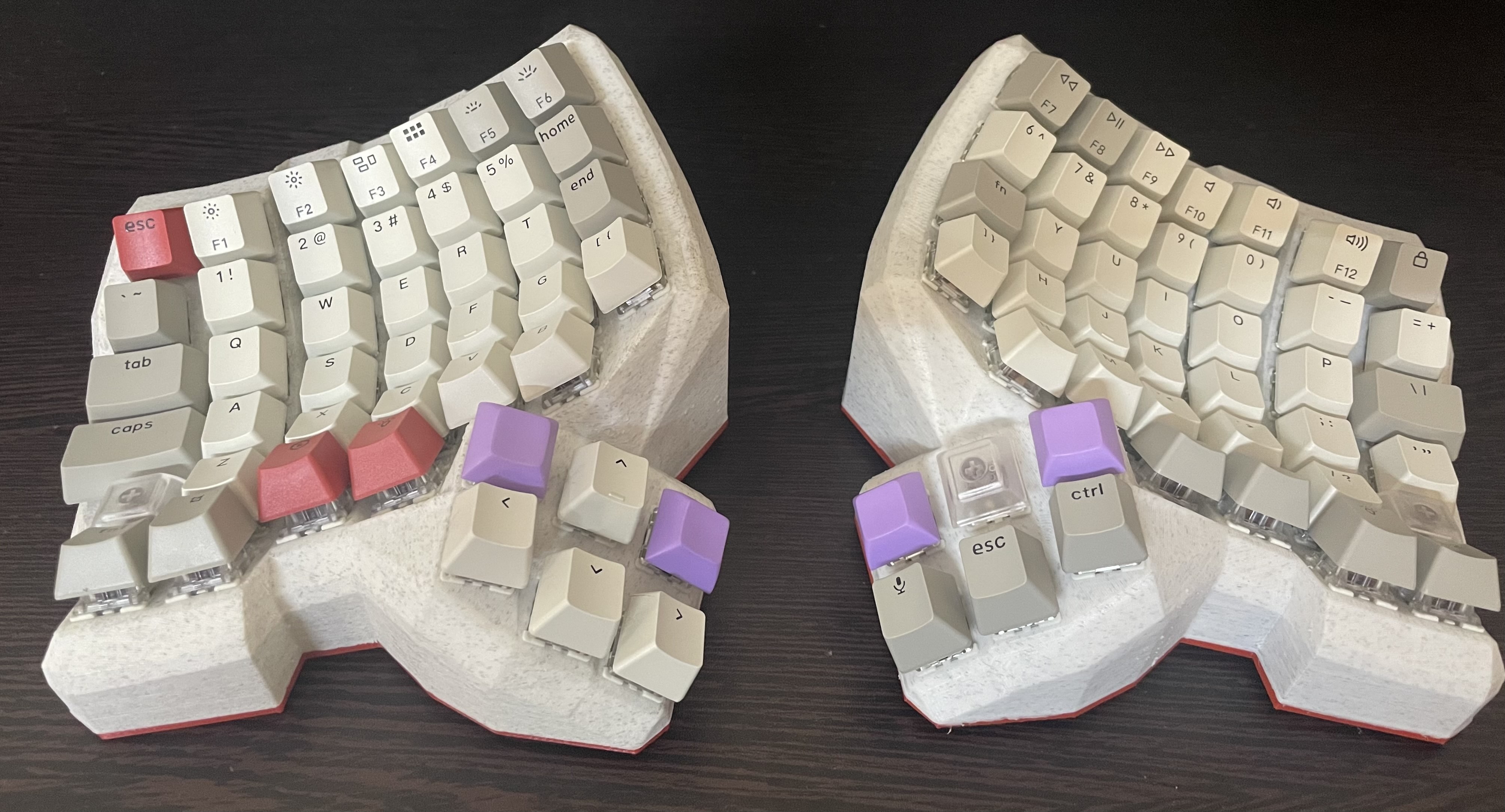
- Row curvature - My fingers are pretty long so I increased the curvature for the middle row a little bit, allowing my longest middle finger to travel freely between the top and bottom rows. I also reduced it a bit for the first column (where the little finger sits) so its easier to reach the Escape key on the top left
- Note: I ended up mapping the Caps Lock key to Escape instead. Highly recommended!
Once I was satisfied with the results, it was a simple matter to export the STL files from OpenSCAD and get them 3D printed. I used 3ding.in as they have a good online interface for printing, and they can ship all over India.
Switches and Keycaps
The problem with specialised keyboards like the Dactyl Manuform, is that they use a different number of keys - and the sizes of the keys are also different - which means a large number of keycaps won’t fit on the board. I went with Keychron’s Retro style Keycap set for the main alphabets and modifier keys, and bought blank keycaps from MecKeys for the remaining ones. I got the switches (Gateron browns) from Meckeys as well.
Note: I also recommend getting the Hot-Swappable switch sockets, they make soldering relatively easy and ensure you can replace switches when you feel like it, something that’s not possible in Kevin’s approach of soldering the switches together with a copper strip.
Microcontrollers
At first I wanted to stick with my tried and tested Arduino Pro Micro, but then I also wanted a Bluetooth wireless connection. The Pro Micro doesn’t have bluetooth onboard and setting up an extra module with the firmware sounded too challenging for me. I ended up buying the Nice! Nano v2 board from rectangles.store.
Be aware that if you want to build a truly split keyboard, you need to get two microcontrollers, one for each half. And obviously, if you want the two halves to be wireless, you need both of them to have Bluetooth. If you’re willing to go wired, this is a good space to save some costs - You can get 2 Pro Micro clones from https://robu.in for less than the cost of a single Nice! nano. You can even save further by going to a Micro-USB board instead of USB-C.
Firmware
I didn’t have much choice here - the two most famous and feature complete firmwares available for such keyboards are QMK and ZMK.
ZMK was the only one with Bluetooth support for the split halves and supporting the Nice! nano v2, so I went with that. My configuration and firmware build is available at GitHub.
Misc. Electrical Supplies
https://robu.in is the place to go to for hobby electronics in India. I got 2 Lithium ion batteries and a bunch of smaller items like controller legs, wires, soldering equipment, screws and standoffs, power switches etc. over there.
Summary of Parts and Cost
Note that the costs are approximate in some places, it has been a long time since I built the board and have lost track of some invoices.
| Component | Source | Cost (approx) |
|---|---|---|
| 3D Printed cases | 3ding.in | ₹ 4,000 |
| Nice! Nano v2 (x2) | Rectangles.store | ₹ 4,700 |
| Keycaps (Keychron) | keychron.in | ₹ 2,000 |
| Switches and Keycaps | meckeys.in | ₹ 4,000 |
| Batteries - Samsung 18650, 2200 mAh (x2) | robu.in | ₹ 1,000 |
| Misc. electronics and soldering supplies | robu.in | ₹ 2,000 |
| Total | ₹ 20,000 |
Wiring
The build vlog and abstracthat’s GitHub documentation talks about this in a much more detail than I can, so I recommend going through those if you made it this far (Congrats and Godspeed 🫡)
Just pay attention to the rows and columns as you solder them together, and keep track of which pin on the controller you’re connecting each row/column too. You’ll need to set those pins in the config.